Explore our manufactured solutions engineered under strict IATF 16949 and ISO 13485 quality systems, ranging from mission-critical automotive units to ultra-stable communication modules.
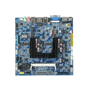
High-Quality Vehicle Control Unit (VCU) PCB Assembly Service, Factory
Explore Specification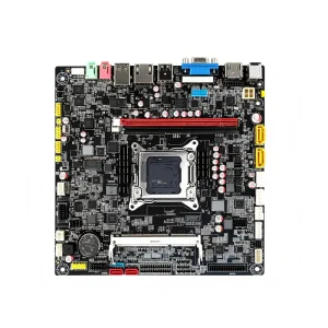
China Repeater PCB Assembly Service, Factory
Explore Specification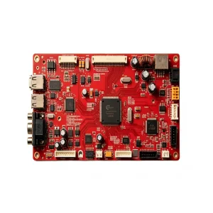
China Intercoms PCBA Assembly--STHL Service, Factory
Explore Specification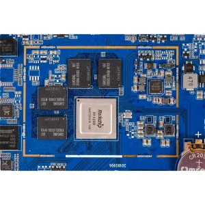
High-Quality Laptop PCB Assembly Service, Factory
Explore Specification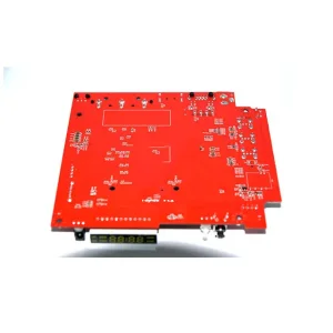
High-Quality Multi-function Printers PCBA Assembly--STHL Manufacturers, Factories
Explore Specification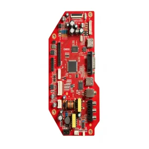
High-Quality Smart Thermostat PCBA Assembly--STHL Manufacturer, Factory
Explore Specification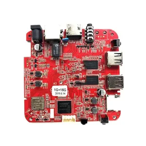
China Ecological Restoration Monitoring Equipment PCB Assembly Manufacturer, Service
Explore Specification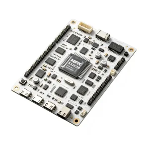
OEM Electronic Fence Vibrator PCB Assembly--STHL Manufacturers, Service
Explore SpecificationFounded in 2006 in the Bao'an high-tech manufacturing corridor of Shenzhen, Shenzhen STHL Electronics Co., Ltd. has developed over two decades into an elite electronics manufacturing services (EMS) partner specializing in challenging RF substrate fabrication, complex surface-mount technology (SMT), and turnkey box build assembly.
High-frequency printed circuit boards fabricated with Rogers advanced materials demand dramatically different thermal, chemical, and mechanical considerations compared to ordinary FR-4. From tightly maintained dielectric constants (εr) to minimal dissipation factors (tanδ) across gigahertz spectra, STHL provides hardware engineers, telecommunications OEMs, and defense contractors with an accountable, single-source manufacturing platform.
At operating frequencies crossing 3 GHz into 77–81 GHz millimeter-wave regimes, signal attenuation shifts from copper-conductive loss dominance to dielectric substrate dissipation and phase dispersion. Ordinary FR-4 exhibits an unstable dielectric constant ranging wildly between 4.2 and 4.8 across operating temperatures, causing unpredictable phase drift and insertion losses.
By implementing authentic Rogers thermoset hydrocarbon laminates (RO4000 series) and ceramic-filled PTFE composites (RO3000 and RT/duroid series), STHL secures minimal electrical loss, ultra-flat thermal coefficient of dielectric constant (TCDk), and uniform mechanical CTE matching electrodeposited copper.
A granular engineering benchmark illustrating dielectric constant stability, dissipation factors, thermal conductivity, and structural properties essential for microwave RF circuit designers.
| Material Series | Dielectric Composition | Dk (εr @ 10GHz) | Df (tanδ @ 10GHz) | Thermal Cond. (W/m/K) | Z-Axis CTE (ppm/°C) | Moisture Abs. (%) | Target RF Bandwidth |
|---|---|---|---|---|---|---|---|
| Rogers RO4350B | Hydrocarbon / Ceramic / Glass | 3.48 ± 0.05 | 0.0037 | 0.69 | 31 | 0.06 | DC to 30 GHz |
| Rogers RO4003C | Hydrocarbon / Ceramic Laminate | 3.38 ± 0.05 | 0.0027 | 0.71 | 46 | 0.04 | DC to 40 GHz |
| Rogers RO3003 | Ceramic-filled PTFE Composite | 3.00 ± 0.04 | 0.0010 | 0.50 | 25 | 0.04 | 77–81 GHz Radar |
| Rogers RT/duroid 5880 | Glass Microfiber Reinforced PTFE | 2.20 ± 0.02 | 0.0009 | 0.20 | 137 | 0.02 | Ku, K, Ka Bands |
| Rogers RT/duroid 6002 | PTFE / Ceramic Composite | 2.94 ± 0.04 | 0.0012 | 0.60 | 24 | 0.02 | Phased Array Defense |
| Standard FR-4 | Woven E-Glass / Epoxy Resin | 4.40 ± 0.30 | 0.0200 | 0.25 | 60–80 | 0.20 | < 2.5 GHz Only |
PTFE-based Rogers substrates require chemical surface activation prior to through-hole plating. STHL utilizes automated plasma gas (CF4/O2) chamber treatment to clean drilled via walls and provide superior copper seed adhesion.
In high-speed digital and millimeter-wave designs crossing 28 Gbps NRZ and 56G/112G PAM4, via stubs act as open resonant transmission lines. STHL achieves precision Z-axis depth backdrilling with stub residuals under 0.15mm.
High-frequency currents flow exclusively along the outer copper conductor boundary. We deploy Electroless Nickel Electroless Palladium Immersion Gold (ENEPIG) and Immersion Silver to bypass nickel magnetic insertion losses entirely.
To reduce raw material costs without compromising high-frequency RF routing, STHL manufactures hybrid stackups bonding outer Rogers layers (RO4350B) with inner low-cost FR-4 cores using matched prepregs like Rogers RO4450F.
Across telecommunications, intelligent automotive mobility, avionics, and high-precision medicine, Rogers substrates assembled by STHL deliver unwavering signal fidelity.
In modern cellular networks, base transceiver stations utilize active antenna systems with 64T64R configurations. Low passive intermodulation (PIM) and stable dielectric constant tolerances ensure uniform beamforming phase weights across wide thermal swings (-40°C to +85°C).
Autonomous emergency braking (AEB) and blind-spot detection rely on frequency modulated continuous wave (FMCW) radar. Assembled using RO3003 ceramic PTFE, STHL boards ensure microstrip patch antennas maintain sub-millimeter wavelength precision with zero delamination.
Low-Earth-orbit (LEO) constellations and satellite transponders operate in the Ka, Ku, and Q bands. Our IPC Class 3 certified PCB processing with RT/duroid substrates avoids outgassing under deep-space vacuum conditions while dissipating extreme radiation energy.
High-density data centers utilize QSFP-DD and OSFP transceivers routing 100 Gbps per lane optical DSP signals. Micro-loss hydrocarbon laminates eliminate jitter, inter-symbol interference (ISI), and signal reflections across tight BGA break-out routing.
In thermal ablation therapy and MRI magnetic tracking devices, high-power RF energy must be steered with zero thermal dissipation into surrounding hardware. Rogers high-thermal-conductivity laminates prevent dangerous hot-spots on surgical end-effectors.
E-band wireless backhauls connecting smart cities and automated factory cells require low phase-noise up/down converters. STHL delivers tightly toleranced coplanar waveguide (CPW) geometries etched down to 3 mil line/space widths.
Zero-Downtime Raw Substrate Availability
While European and North American EMS facilities encounter 8- to 16-week lead times for genuine Rogers materials, STHL maintains strategic standing consignment inventory agreements in the Pearl River Delta. Authentic RO4003C, RO4350B, RO3003, and RT/duroid sheets are stocked locally in various copper weights (0.5 oz, 1 oz, reverse-treated foil) and core thicknesses (8 mil, 12 mil, 20 mil, 30 mil, 60 mil).
Navigating global electronics production requires both technical rigor and commercial efficiency. STHL bridges this gap by combining Chinese domestic engineering supply chains with stringent Western compliance systems.
As next-generation radar systems, 6G communications, and artificial intelligence compute architectures converge, STHL is expanding its high-frequency substrate assembly roadmap.
Developing ultra-smooth copper foil treatments (profile roughness Rz < 0.6 μm) to minimize resistive conductor skin-effect attenuation up to 140 GHz D-band transmissions.
Integrating mechanical press-fit and bonded copper thermal blocks directly underneath power amplifiers (PAs) and high-heat GaN modules for direct conductive dissipation.
Upgrading line and space patterning to sub-50 μm tolerances, guaranteeing precise characteristic impedance control (Zo) across coplanar waveguides with zero undercut.
Partnering with Rogers Corporation to integrate next-generation bio-based and halogen-free low-loss materials compliant with expanding European REACH RoHS bans.
High-frequency assemblies cannot be verified through basic visual or continuity testing alone. STHL executes rigorous RF parametric, optical, and mechanical validation protocols.
Every RF production panel incorporates designated microstrip coupon structures. Using calibrated VNAs up to 67 GHz, our engineers verify return loss (S11), insertion loss (S21), and time-domain reflectometry (TDR) impedance tolerances.
High-frequency QFN, BGA, and LGA packages feature hidden solder joints underneath ground planes. STHL uses high-resolution oblique 3D X-ray systems to verify voiding levels are kept well below 10%, eliminating thermal degradation and ground drift.
Microsection destructive testing verifies through-hole copper plating thickness (averaging ≥ 25 μm according to IPC-6012 Class 3), resin recession, copper foil peel strength, and via filling completeness inside our in-house metallurgical laboratory.
Engineered for mission-critical reliability across healthcare monitoring, industrial control, smart automotive HUDs, and high-efficiency optical networking equipment.
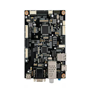
High-Quality Smart Blood Glucose Monitor PCB Assembly--STHL Manufacturers, Factories
Explore Specification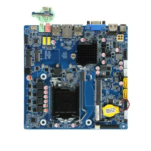
High-Quality Water Heater Controller PCB Assembly Service, Factory
Explore Specification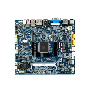
China Optical Transceiver PCB Assembly Service, Factory
Explore Specification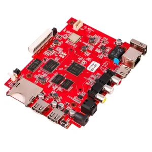
China Blood Pressure Monitor PCB Assembly--STHL Manufacturer, Service
Explore Specification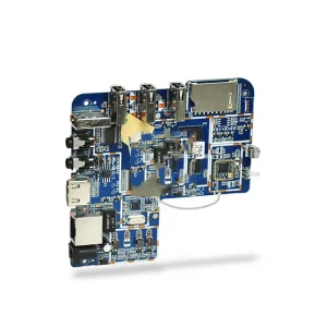
OEM Head-Up Display (HUD) PCB Assembly Manufacturers, Factory
Explore Specification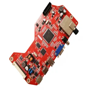
High-Quality Smart Dimmer Switch PCBA Assembly--STHL Manufacturer, Factories
Explore Specification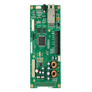
OEM LED Rigid Strip Light PCB Assembly--STHL Service, Factory
Explore Specification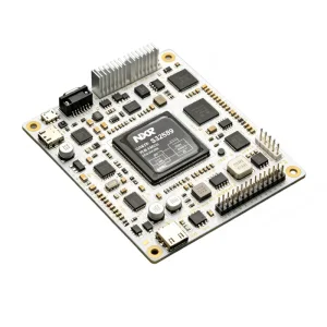
High-Quality Surgical Navigation System PCB Assembly--STHL Manufacturer, Factory
Explore SpecificationIn-depth technical answers addressing common layout challenges, thermal behaviors, stackup budgeting, and manufacturing guidelines for overseas purchasing managers and RF design teams.