
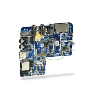
Explore our certified electronic assemblies built with zero MOQ constraints, rigorous IPC Class 3 standards, and comprehensive in-circuit functional testing.
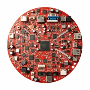
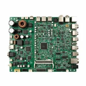
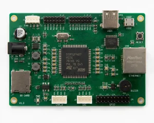
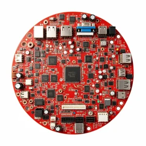
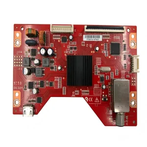
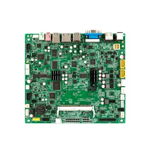
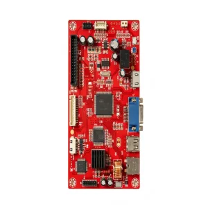
Architectural shifts toward high-density interconnects, 3D mechatronics, and weight-critical electrification ecosystems.
The contemporary electronics manufacturing ecosystem has outpaced standard planar FR-4 capabilities. In high-vibration, space-constrained environments—spanning from automotive powertrain control units to advanced endoscopic surgical arrays—rigid-flex circuit boards have transcended their status as luxury engineering choices to become functional imperatives. By fusing polyimide flexible cores with standard glass-reinforced FR-4 substrates, rigid-flex technology eliminates bulky wire harnesses, discrete pin headers, and prone-to-failure soldered interconnects.
From an operational standpoint, modern rigid-flex fabrication requires extreme precision in mechanical routing, laser drilling, and adhesive flow control. Adhesiveless polyimide laminates combined with modified acrylic or epoxy prepregs allow controlled impedance matching for high-speed differential pairs exceeding 25 Gbps. As OEM hardware designers navigate strict thermal envelopes and sub-millimeter clearances, turnkey PCB assembly factories must bridge bare-board lamination physics with automated SMT placement accuracy.
Rigid-flex printed circuit boards unlock genuine 3D spatial integration. Instead of stacking separate boards linked via ribbon cables, a unified rigid-flex substrate bends across compound mechanical angles, cutting chassis volume by up to 60%.
By eradicating physical board-to-board connectors, parasitic capacitance and inductance are drastically minimized. Continuous ground reference planes across rigid-to-flex transitions provide uninterrupted 50Ω single-ended and 100Ω differential impedance.
Eliminating manual wiring assemblies removes the primary failure vector in high-shock and high-vibration applications. Our assemblies withstand thermal cycling from -40°C to +125°C under continuous mechanical acceleration.
Quantifiable parameters engineered for low-loss high-speed signaling, extreme dynamic bending, and multi-layer HDI microvia structures.
| Technical Metric | Standard Capability | Advanced / HDI Rigid-Flex | Quality Verification Baseline |
|---|---|---|---|
| Layer Count Range | 2 to 12 Layers (Rigid + Flex) | Up to 24 Layers (Multi-core Polyimide) | IPC-6013 Class 3 Microsection Analysis |
| Base Flex Core Substrate | Adhesiveless Polyimide (12.5µm - 50µm) | Low-Dk/Df Polyimide & LCP (Liquid Crystal) | IPC-TM-650 Dielectric Constant Testing |
| Rigid Substrates | High-Tg FR-4 (Tg 170°C - 180°C) | Rogers High Frequency, Polyimide, Halogen-Free | Differential Scanning Calorimetry (DSC) |
| Min. Line Width / Spacing | 3.0 mil / 3.0 mil (75µm / 75µm) | 1.8 mil / 1.8 mil (45µm / 45µm) via mSAP | Automated Optical Inspection (AOI) |
| Microvia / Blind & Buried | Laser drilled 0.10mm (4 mil) | Stacked / Staggered 0.075mm Microvias | High-Magnification Industrial X-Ray Inspection |
| Surface Finish Chemistry | ENIG (Electroless Nickel Immersion Gold) | ENEPIG, Immersion Silver, Hard Gold Plating | XRF Plating Thickness Verification |
| Dynamic Flexing Endurance | > 50,000 cycles (Static bend radius 6x) | > 1,000,000 dynamic cycles (Bend radius 10x) | Custom Mechanical Dynamic Flex Endurance Rig |
Deployment scenarios engineered to solve volumetric density and mechanical durability challenges.
ISO 13485 compliant manufacturing for swallowable camera capsules, handheld ultrasonic scanners, and diagnostic analyzers requiring zero flex-hinge failures and biocompatible encapsulation.
IATF 16949 verified battery management systems (BMS), radar transceivers, and steer-by-wire sensors where thermal expansion, copper work-hardening resistance, and vibration tolerance are non-negotiable.
Rigid-flex interconnects for Inertial Navigation Systems (INS) and flight control computers operating under high G-forces and sudden pressure gradients with zero risk of solder fatigue or connector detachment.
High-efficiency buck-boost converters and smart power monitoring systems integrating heavy copper rigid cores with flexible routing to navigate modular DIN-rail enclosures seamlessly.
How progressive material science, additive manufacturing, and automated assembly are redefining flexible hybrid electronics.
Mainstreaming 1/3 oz and 1/4 oz rolled annealed copper with adhesiveless cast polyimide to decrease total stack profile under 0.4mm for wearable mechatronics.
Adopting LCP substrates for 5G mmWave and 6G edge applications due to near-zero moisture absorption (0.04%) and exceptional high-frequency dielectric stability up to 110 GHz.
Burying micro-passives and ultra-thin bare dies inside the inner rigid polyimide layers, transforming empty substrates into functional, shielded silicon-carrier engines.
Integrating optical waveguides into flexible substrate backplanes to enable terabit-level inter-chassis communication with total immunity to electromagnetic interference (EMI).
From complex network switches to precision vision systems, see how STHL delivers turnkey excellence from component procurement to final enclosure assembly.
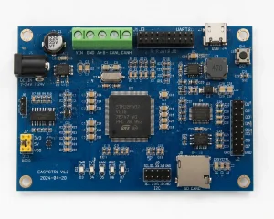
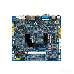
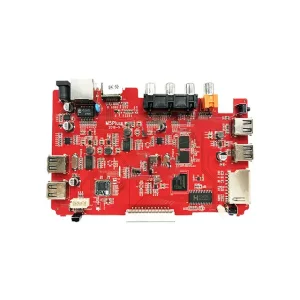
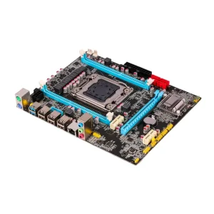
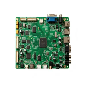
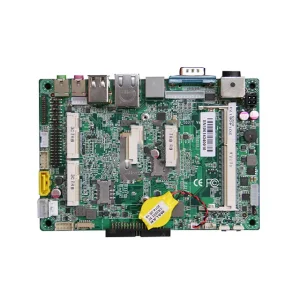
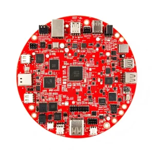
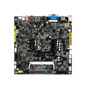
Every work order running through our 10,000+ m² facility is tracked via integrated ERP & MES systems to ensure zero component obsolescence, complete trace integrity, and flawless solder joints.
Our 7 automated SMT lines deploy 3D SPI (Solder Paste Inspection) before component mounting to eliminate bridging and insufficient volume, followed by multi-angle 3D AOI and 100% X-ray inspection for high-density BGA, QFN, and fine-pitch IC arrays.
Sourcing across 100+ authorized global distribution channels with lot-level barcoding protects your builds from cloned silicon. Our component engineering team actively provides form-fit-function alternative recommendations for long-lead parts.
For outdoor environmental monitoring, water quality analyzers, and mission-critical power supplies, automated selective conformal coating lines apply uniform acrylic, polyurethane, or silicone barriers guarding against humidity, chemical vapors, and dust.
Engineering answers to technical inquiries on stack-up design, thermal profiling, minimum bend radii, and global delivery guarantees.
The standard guideline for static flex circuits (flex-to-fit during installation) is a minimum bend radius of 6× the overall flexible substrate thickness. For continuous dynamic flexing applications (such as hinges or sliding robotics), the minimum bend radius must be kept at 10× to 12× the total flex thickness, utilizing rolled annealed (RA) copper cores rather than electrodeposited (ED) foils to prevent mechanical grain fracturing.
Delamination primarily results from trapped moisture within polyimide films or unmatched CTE (Coefficient of Thermal Expansion) stress. STHL implements mandatory high-vacuum pre-baking protocols prior to SMT reflow, combined with staggered prepreg step-downs and no-flow (or low-flow) epoxy prepregs at the interface to establish strong mechanical shear adhesion without resin bleeding onto exposed flex regions.
Yes. However, best DFM practices dictate keeping through-hole (THT) leads and bulky passive components on the reinforced rigid sections. In instances where sensors or LEDs must be mounted directly within the flexible area, STHL employs localized polyimide or FR-4 backing stiffeners under the SMT pads to prevent solder joint shear during flexing.
We execute standard Non-Disclosure Agreements (NDAs) prior to receiving your CAD, Gerber, BOM, or proprietary firmware files. Our internal IT infrastructure segregates customer production files via role-based access controls, ensuring designs are solely exposed to the dedicated project engineering and CAM validation squads.
STHL operates with absolute zero MOQ. You can build 5 to 50 prototype units for mechanical validation, clinical trials, or design verification testing (DVT), and subsequently scale up to mass production on the very same automated SMT lines without requiring requalification or redesign.
Every shipment is verified through multi-tier testing: 100% bare-board electrical testing (flying probe or dedicated bed-of-nails fixture), 3D automated optical inspection (AOI), 3D X-ray inspection for bottom-terminated components, plus dedicated functional testing (FCT) developed around your specific firmware flashing and stimulus-response requirements.