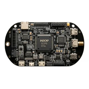
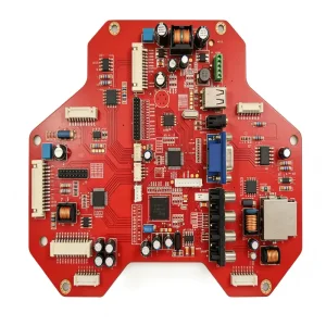
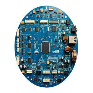
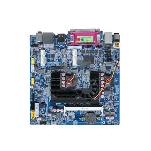
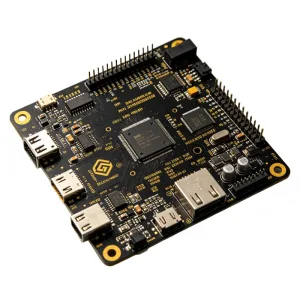
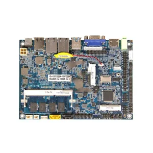
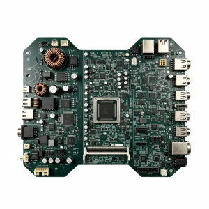
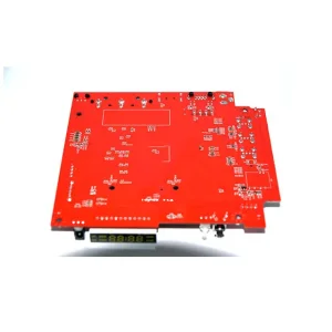
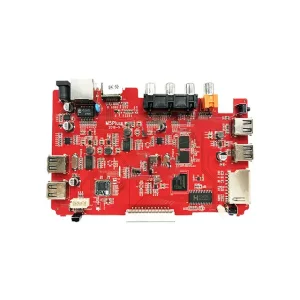
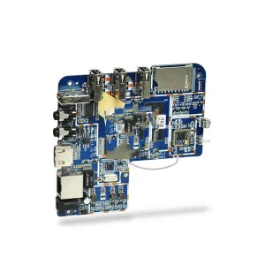
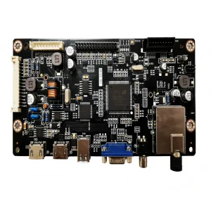
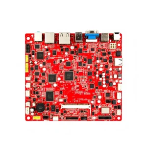
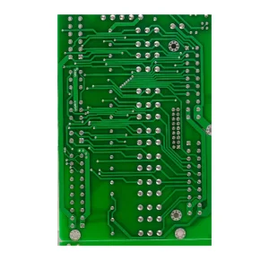
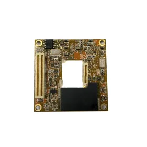
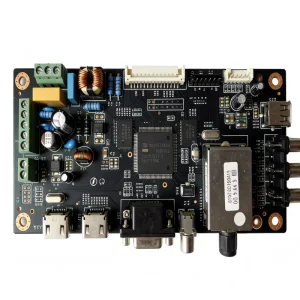
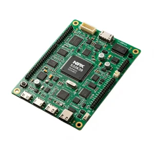
Explore production modules successfully delivered through our fast-track manufacturing lines, operating under strict IPC Class 3 and Class 2 assembly criteria.
How rapid miniaturization, dynamic spatial limitations, and high-speed data transmission are transforming industrial electronics procurement strategies.
Traditional wire harnesses and multi-board pin header systems increase mass, assembly failure vectors, and overall enclosure volumes. High-density flex circuits (FPC) reduce total packaging weight by up to 70% and volume by up to 60%, providing dynamic flexing capabilities capable of withstanding millions of operational flex cycles in robotics, medical hinges, and portable edge devices.
Hardware sprint cycles now emulate agile software frameworks. Waiting 4-6 weeks for prototype validation stalls engineering progress. Our OEM Quick Turn Flex PCB manufacturing architecture eliminates tooling wait times through direct laser imaging (LDI), roll-to-roll laser profile routing, and algorithmic DFM feedback, converting standard multi-week lead times into a 24- to 72-hour reality.
Modern telematics and medical diagnostics operate under stringent signal loss budgets and extreme thermal swings. Utilizing adhesiveless flexible copper clad laminates (FCCL) with polyimide cores ensures uniform dielectric constants (Dk 3.2-3.4) at gigahertz frequencies, minimal insertion loss, and stable continuous thermal performance across operating temperatures ranging from -40°C to +125°C.
Inside the operational workflows, cleanroom disciplines, and proprietary CAM verification mechanisms powering high-velocity turnaround times.
Every Gerber, ODB++, and stack-up file submitted undergoes an automated 48-point design-for-manufacturability audit. Our CAM engineers identify unradiused trace corners, inadequate teardropping, dynamic bend-zone vias, and coverlay sliver risks within hours, preventing fabrication rework before copper panels enter chemical etching.
Reliable flex circuitry requires targeted mechanical rigidity at connector junctions and SMT component zones. We fabricate multi-zone boards incorporating FR-4 stiffeners for high-pin BGA/QFN surface-mounting, thin stainless steel or aluminum stiffeners for heat sinking, and polyimide backings for zero-insertion-force (ZIF) connector finger thickness control.
Placing micro-components onto supple polyimide membranes necessitates proprietary precision vacuum-nest fixtures, high-accuracy vision alignment pick-and-place lines, and localized reflow temperature profiling. Our Shenzhen facility employs custom magnetic carriers and dedicated thermal profiling to eliminate warpage, solder bridging, and component tombstoning.
From aerospace vibration stress to clinical medical grade longevity, examine how our quick turn flex PCB boards perform in real-world deployment.
Flexible circuits are non-negotiable for medical equipment where ergonomics, weight, and signal cleanliness are critical. In patient-worn vital monitors, endoscopes, and ultrasonic probes, our thin-core (0.5 mil polyimide) biocompatible assemblies provide continuous flex endurance, moisture resistance, and seamless IPC-6013 Class 3 compliance.
Certified under IATF 16949, our automotive flex assemblies withstand intense ambient engine-compartment temperatures, cyclic vibration, and chemical exposure. Typical architectures include steering angle sensors, battery management system (BMS) bus interconnects, LiDAR sensor heads, and roof-mounted infotainment connectivity modules.
Robotic end-effectors, multi-axis cobot arms, and programmable logic controller (PLC) modules experience millions of torsional movements per year. Our high-flex rolled-annealed (RA) copper foil stack-ups prevent work-hardening microfractures, providing uninterrupted industrial field bus communication and deterministic power delivery.
Our Quality Management Systems (QMS) enforce traceability, rigorous testing, and documented process controls from bare polyimide laminate to final packed module.
Operating our 10,000+ m² facility under ISO 9001, ISO 13485 (Medical Devices), IATF 16949 (Automotive), and ISO 14001 ensures audited quality standards across your build. Solder integrity conforms strictly to IPC-A-610 Class 2 and Class 3 criteria with dedicated RoHS and REACH lead-free adherence.
Flexible circuit traces and fine-pitch components require specialized inspection regimes. We apply high-resolution Automated Optical Inspection (AOI) to bare etched traces, followed by 3D AXI (Automated X-ray Inspection) post-SMT reflow to verify BGA solder ball void ratios, wetting boundaries, and hidden-joint fillets.
Our integrated ERP and Manufacturing Execution System (MES) tags every batch with unique lot tracking barcodes. From bare laminate pre-preg reels to pick-and-place component reels sourced from our certified partner channels (Arrow, Avnet, Digi-Key, Mouser), every board features complete lifecycle verification.
Anticipating next-generation electrical, mechanical, and material demands for 5G, ultra-fine pitch substrates, and harsh environment implementations.
Deploying Liquid Crystal Polymer (LCP) dielectric layers offering minimal moisture absorption (<0.04%) and stable dielectric loss tangents up to 40 GHz for next-gen mmWave antenna integration.
Refining our chemical etching and plating lines to transition from sub-75μm pitch down to sub-30μm line/space dimensions, unlocking ultra-high-density micro-vias on dynamic substrates.
Laminating thin-film resistors and capacitive layers directly within the flex stack-up, eliminating discrete SMT footprints, boosting noise margins, and maximizing spatial design freedom.
Leveraging continuous machine-vision neural networks across the copper roll line to dynamically identify and auto-correct micro-defects in real-time, driving rapid-turn yields past 99.8%.
Comprehensive technical answers to critical engineering, manufacturing, and supply chain questions from OEM procurement specialists.
Review additional production PCBA assemblies engineered for high reliability across environmental monitoring, medical sensing, avionics, and power management.